6. Various#
6.1. Reinforcement calculation#
It is possible to calculate the reinforcement of a structure using the operator CALC_FERRAILLAGE [U4.81.42]. The method used is that of Capra and Maury [R7.04.05]
6.2. Macro to help identify material parameters#
For a certain number of laws of behavior, the identification of material parameters can be relatively complex. Also, some macros have been developed to help users carry out this step, or even business tools under salome_meca. It is about:
DEFI_GLRC [U4.42.06] for the global laws GLRC_DM and GLRC_DAMAGE, which makes it possible to obtain the properties of homogenized concrete from the physical and geometric characteristics of reinforced concrete;
DEFI_MATER_GC [U4.42.07] for (i) the laws of MAZARS or MAZARS_GC using rules from BAEL91, Eurocode 2 or by providing classical material characteristics (ii) for law ENDO_FISS_EXP;
the business tool ARCADE [SU1.11.01] under Salome_meca which makes it possible to identify the parameters of the creep law BETON_BURGER_FP and even to recalibrate them in the case of containment structures;
the business tool for identifying the parameters of the reinforced concrete law DHRC [SU1 .10.01]. Note that the use of this tool can also make it possible to give the realistic linear response for any flexure and membrane sections of reinforced concrete plates, to verify the homogenized properties or to quantify the effects of flexion-membrane coupling for example.
Also worth noting, in a similar register, the existence of the command CALC_ESSAI_GEOMECA [U4.90.21] which makes it possible to verify the relevance of the soil law parameters identified by obtaining the answer on the hardware point for various tests such as monotonous or cyclic triaxial tests, drained or not, drained or not, oedometric tests, etc.
In any case, reference documentation remains an indispensable source of information, knowing that in addition, for some laws, there are EDF, internal Model Identity Sheets that explain identification techniques.
6.3. Pre/post-treatment#
6.3.1. Data verification#
We often need to check the data entry, to be sure, for example, that we have assigned the right geometric characteristics to structural elements, to have them well oriented, that the affected material fields have been assigned to the right groups of cells,…
Visualization tools can be useful to help verify the data layout;
Visualize the orientation of structural elements in SaloméMeca. This is possible by printing the local coordinate system in MED format (cf. [U7.05.21]) and viewing these concepts under salome_meca. An example is shown below.
Visualize with different colors, the mesh groups having a different thickness, having been affected by different materials, etc. To do this, it is necessary to print the desired field in format MED (cf. [U7.05.21]), for example:
IMPR_RESU (FORMAT =” MED “, CONCEPT =( _F (CHAM_MATER = CHMAT), _F (CARA_ELEM = CARELE), _F (CHARGE = CHAR1),),);
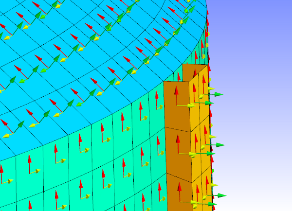
Figure 6.3.1-1 : example of visualizing the orientation of the local coordinate system
In a med file, we then obtain a field called CHMAT_CHAMP_MAT having one mesh value among: 0, 1, 2,… The correspondence between the values: 1, 2, 3… and the names of the materials is written in the message and result files.
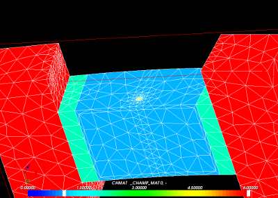
Figure 6.3.1-2 : example of visualization of material assignments under Salomé
6.3.2. Post-treatments#
For post-treatments, numerous possibilities are offered to the user, which cannot be detailed. Let’s just mention a few options specific to Civil Engineering:
Thanks to the operator CALC_CHAMP [U4.81.04], numerous options are available depending on the modeling or the law of behavior used, including:
isolate deformations related to natural creep EPFP_XXXX or desiccation EPFD_XXXX;
isolate thermal deformations, endogenous shrinkage or desiccation EPVC_XXXX;
calculate the stresses projected onto the skin of a volume (for example on the facings of a hydraulic structure) SIRO_ELEM;
calculate the energies dissipated DISS_XXXX, ECIN_ELEM,..
- Visualize the stress or deformation fields in multi-fiber beams (POU_D_EM) and multi-layer shells (DKT) using the command IMPR_RESU_SP, cf.
Figure 6.3.2-1: Example of visualization at sub-points
Visualize the internal forces and moments for structural elements, cf. [U7.05.21] §6
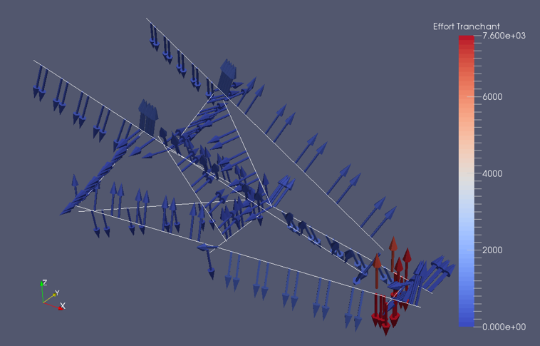
Figure 6.3.2-2Example of visualizing shear forces on beams
Extract forces or deformations at any point in a shell using the POST_COQUE [U4.81.23] operator.
Trace the crack path and calculate the crack opening (\(2D\) only) from a non-local damage calculation (GRAD_VARI) using the POST_ENDO_FISS [U4.86.01] operator.
Fragility curve construction with POST_DYNA_ALEA, [U4.84.04], and [U2.08.05].