1. Theory#
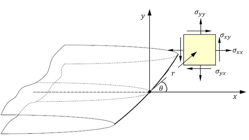
Based on isotropic-linear-elasticity theory, when an elastic cracked body is subjected to external forces (see Fig.1), the stress field in the vicinity of a crack tip can be expressed by the Williams” expansion. The stresses near the crack-tip can be written according to equations 1-2, where \({\mathrm{\sigma }}_{\mathit{ij}}\) is the stress tensor, \(r\) represents the distance of element from crack tip, and \(\mathrm{\theta }\) is the angle of element with respect to a polar axes located at the crack tip [1].
\({\mathrm{\sigma }}_{\mathit{rr}}=\frac{{K}_{1}}{\sqrt{(2\mathrm{\pi }r)}}(\frac{5}{4}\mathrm{cos}(\frac{\mathrm{\theta }}{2})-\frac{1}{4}\mathrm{cos}(\frac{3\mathrm{\theta }}{2}))+\frac{{K}_{2}}{\sqrt{(2\mathrm{\pi }r)}}(\frac{-5}{4}\mathrm{sin}(\frac{\mathrm{\theta }}{2})+\frac{3}{4}\mathrm{sin}(\frac{3\mathrm{\theta }}{2}))+T{\mathrm{cos}}^{2}(\mathrm{\theta })\) Equation 1
\({\mathrm{\sigma }}_{\mathrm{\theta }\mathrm{\theta }}=\frac{{K}_{1}}{\sqrt{(2\mathrm{\pi }r)}}(\frac{3}{4}\mathrm{cos}(\frac{\mathrm{\theta }}{2})+\frac{1}{4}\mathrm{cos}(\frac{3\mathrm{\theta }}{2}))+\frac{{K}_{2}}{\sqrt{(2\mathrm{\pi }r)}}(\frac{-3}{4}\mathrm{sin}(\frac{\mathrm{\theta }}{2})+\frac{3}{4}\mathrm{sin}(\frac{3\mathrm{\theta }}{2}))+T{\mathrm{sin}}^{2}(\mathrm{\theta })\) Equation 2
|
Fig.1 Stress in a polar coordinate system ahead of a crack in an infinite plate |
The non-singular term is known as T-stress, and characterises the crack tip constraint; this is particularly useful in the assessment of the integrity of structures containing defects. A robust method for obtaining T-stress is via the displacement field along the crack faces. This method is based on the asymptotic development of the displacement field in the crack tip. For \(\mathrm{\theta }=-\mathrm{\pi }\) or \(\mathrm{\theta }=+\mathrm{\pi }\) the singular term of \({\mathrm{\sigma }}_{\mathit{rr}}\) vanished and therefore near the crack tip, T-stress can be represented by:
\(T={E}^{\text{'}}\frac{[{U}_{\mathrm{\theta }=\mathrm{\pi }}(r)]-[{U}_{\mathrm{\theta }=\mathrm{\pi }}(0)]}{r}\)
Where \([U]\) is the displacement step between the crack lips and therefore \([{U}_{\mathrm{\theta }=\mathrm{\pi }}(0)]\) denotes displacement of crack tip; details of the method are given elsewhere [2]. \({E}^{\text{'}}\) is defined for plane stress and plane strain conditions as:
\({E}^{\text{'}}=\left\{\begin{array}{c}E\\ \frac{E}{1-{\mathrm{\upsilon }}^{2}}\end{array}\begin{array}{c}\mathit{Plane}\mathit{stress}\\ \mathit{Plane}\mathit{strain}\end{array}\right\}\)
Note:
Itis alsopossito computet-stress**according to the stress fields, but the values of the vector forced on the lips of crack are less accurate than displacements (resulting from a**stress singularity in crack tip) .
**The user must take care* to refine the mesh in the vicinity of crack tip*so that* enough points are available for extrapolation.
The method used here is theoretically less accurate than than the integration integral method for computation of T-stress since the integral is taken over a domain of elements surrounding the crack and errors in local solution parameters have less effect on the evaluated quantities.*than than the the integration integral method for computation of T-stress sets for the calculation of T-stress is simpler than In the J-integral Approach.thus**it makes possible to obtain easily relatively reliable values of**T-Stress**for any *Type of*mesh strategy. The comparison of the different methods of calculating is always useful to estimate the accuracy of the results obtained. *