1. General description of the method#
1.1. Principle of the calculations carried out#
Whether the defect in question is elliptical or semi-elliptical in shape, the general principle of the method remains exactly the same at the level of each of the points of the defect in question.
In a first step, on the one hand, from the analysis of the stresses resulting from the numerical analysis of linear elasticity on the healthy mesh (without mesh defects) and, on the other hand, of the residual stresses provided by the user, the factor of intensity of the elastic stresses is calculated based on an analytical formula. It is essentially at the level of this first step that the difference in treatment between the elliptical defect and the semi-elliptical defect lies in that the analytical formula on which the analysis is based differs depending on whether the defect is elliptical or semi-elliptical. In fact, in the first case, this analytical formula corresponds to that for a band defect in an infinite medium with some appropriate modifications so that it applies to the case of an elliptical defect. On the other hand, in the second case, this analytical formula corresponds to the method of influence coefficients which is codified in RSE -M.
In a second step, the application of the so-called « correction-b » method to the elastic stress intensity factor makes it possible to deduce the elasto-plastic stress intensity factor (also therefore qualified as « plastically corrected »). Thus, during this second stage, the methodology for determining the stress intensity factor corrected plastically from the elastic stress intensity factor remains identical between the case of the elliptical defect and the case of the elliptical defect.
1.2. Method validity framework \({K}_{\beta }\)#
The proposed method applies to an under-coating defect located in the current part of a ferritic steel tank lined on the inner wall with austenitic stainless steel subjected to either:
to a thermal transient applied to the internal surface possibly combined with a limited pressure loading
to a pressure-only load.
The so-called « correction-b » correction method is not only valid for a defect under coating whose point located on the side of the coating is strictly at the interface between the coating and the base metal, but the method also remains valid when this last point is slightly offset in the coating or in the base metal.
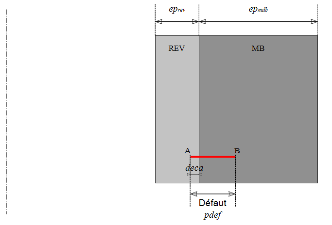
By noting \(\text{pdef}\) the depth of the defect in the radial direction and \({\text{ep}}_{\mathit{rev}}\) (respectively \({\text{ep}}_{\mathit{mdb}}\)) and (respectively) the thickness of the coating (respectively the thickness of the base metal), the RSE -M specifies the following conditions for the validity of the method:
\(\frac{\mid \text{deca}\mid }{{\text{ep}}_{\text{rev}}}\le \mathrm{0,2}\) and \(\frac{\text{pdef}}{{\text{ep}}_{\text{rev}}}\le 3\) and \(\frac{\text{pdef}}{({\text{ep}}_{\text{rev}}+{\text{ep}}_{\text{mdb}})}\mathrm{\le }\frac{1}{\text{10}}\)
All of these parameters are illustrated in Figure 1.2-a
Figure 1.2-1: Undercoating defect diagram

Figure 1.2-a: Undercoating defect diagram
For the case of the elliptical defect, the following three positions with respect to the interface between the coating and the base metal are thus possible:
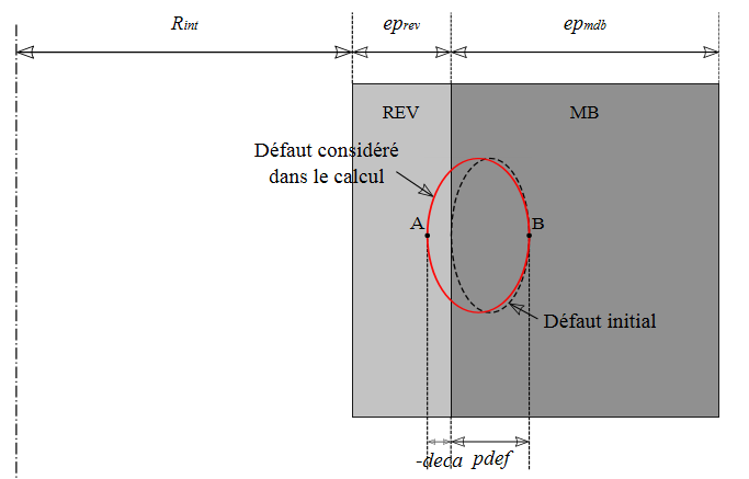
slight offset of the defect in the coating (offset counted negatively, \(\text{deca}<0\))
defect located strictly under the coating (zero offset, \(\text{deca}=0\))
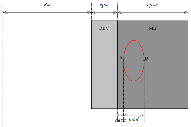
slight offset of the defect in the base metal (offset counted positively, \(\text{deca}>0\))
On the other hand, for the case of the semi-elliptical defect, by nature, only the case of the defect located strictly under the coating (zero offset, \(\text{deca}=0\)) is considered.
1.3. Geometric treatment of the offset for the elliptical defect#
The treatment of the offset of the elliptical defect differs depending on whether this offset is in the coating or in the base metal. In fact, in the case of a shift in the coating, the offset actually corresponds to an extension of the defect by a distance \(\mid \text{deca}\mid\) in the coating while in the case of a shift in the base metal, this offset actually corresponds to a translation of the defect by a distance \(\mid \text{deca}\mid\) into the base metal.
Thus, in the first case (\(\text{deca}<0\)), the effective depth of the defect in the radial direction is not \(\text{pdef}\) but \(\text{pdef}+\mid \text{deca}\mid\). Point B is located in the base metal at a distance \(\text{pdef}\) from the interface between the coating and the base metal. Point A is located in the liner at a distance \(\mid \text{deca}\mid\) from the interface between the liner and the base metal. This first case is illustrated in Figure 1.3-a.
On the other hand, in the second case (\(\text{deca}>0\)), the effective depth of the defect in the radial direction is indeed \(\text{pdef}\). Point B is located in the base metal at a distance \(\text{pdef}+\text{deca}\) from the interface between the coating and the base metal. Point A is located in the base metal at a distance \(\text{deca}\) from the interface between the coating and the base metal. This second case is illustrated in Figure 1.3-b.

Figure 1.3-a: Offset elliptical defect in the coating

Figure 1.3-b: Offset elliptical defect in the base metal
Note that, by default, the value \(\mathit{deca}\mathrm{=}\mathrm{-}2.{10}^{\mathrm{-}4}\) is chosen in POST_K_BETA for the elliptical default. In other words, by default in POST_K_BETA, the elliptical defect is considered to be very slightly offset in the coating.