Modeling the grid-pencil bond DIS_GRICRA#
Behavior DIS_GRICRA is used to model the translational and rotational behavior of grid-pencil connection springs in fuel assemblies. The law of behavior was designed to be used with discretes with two nodes MECA_DIS_TR_L [bib2].
General presentation#
The pens are held in the grid cells by the system of bumps and springs shown in the following figure:
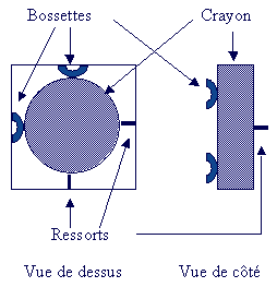
Diagram of a grid cell.#
The pencil is therefore held in the grid cell by six contact points (see r5.03.17-gricra-cellule_de_grille): four bumps and two springs. It is possible to model each of the contact elements (bumps and springs) using discrete elements, to which a law of friction of type DIS_CHOC is assigned. Such modeling makes it possible to represent in a satisfactory manner the behavior of a grid cell in translation (extraction of the pencil) and in rotation. However, such a method has the following disadvantages:
Complexity of the mesh to be produced, because six discrete ones are needed per grid cell (or per grid in a homogenized model), with different heights for the bumps and the springs.
Complexity in defining the characteristics of discretes, because it is necessary to differentiate between bumps and springs
Modeling asymmetry (boss on one side and coming out in opposition), while the homogenized behavior on a grid can be considered as symmetric, taking into account the alternation of the orientation of the grid cells in the grids.
Difficulties in identifying the parameters of discrete behavior at the scale of a fuel assembly.
An equivalent modeling called DIS_GRICRA has been proposed, which makes it possible to find the same behavior as the system of six discretes in translation and rotation, while avoiding the disadvantages mentioned above:
The grid-pencil connection is modelled by four discrete elements crossed in the same plane, which simplifies the meshing and makes it possible to symmetrize the problem.
All four elements are assigned the same parameters for the DIS_GRICRA law of behavior.
Translational and rotational behaviors are treated separately, which facilitates the identification of parameters.
To overcome “zero pivot” problems, it is possible to penalize local stiffness in translation.
- note
In order to correctly represent the behavior of the connection in all directions, especially in rotation, it is necessary to use four discretes arranged in a cross, the pencil being linked to the discretes in the middle of the cross-shaped device.
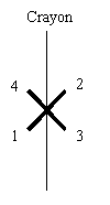
Device of 4 discrete crosses necessary for modeling the behavior of a grid cell.#
Definition of the local coordinate system#
The equations of the law of behavior are written in the local discrete coordinate system. Given the orthotropic nature of the behavior in directions tangential to the discrete, the following convention is adopted for the definition of the local coordinate system of the discrete: the axis \(x\) represents the axis of the discrete, the axis \(y\) corresponds to the direction of the pencil, and the axis \(z\) corresponds to the direction of the pencil, and the axis is the axis orthogonal to \(x\) and \(y\). For the angles of rotation, we will note \(\Phi\) the angle of rotation around the axis \(x\) (DRX) and \(\theta\) the angle of rotation around the axis \(z\) (DRZ). We are not interested in the angle of rotation around \(y\) (DRY), because you have to block this rotation (limit condition) in the command file.
With this definition of the local coordinate system, the direction \(y\) is common to all the discretes of the cross system represented in FIG. r5.03.17-gricra-dispositif-en-croix-cellule_de_grille. The direction \(x\) of the discretes 1 and 2 corresponds to the direction \(z\) of the discretes 3 and 4 (and vice versa). Angle \(\Phi\) of 1 and 2 corresponds to angle \(\theta\) of 3 and 4 (and vice versa).
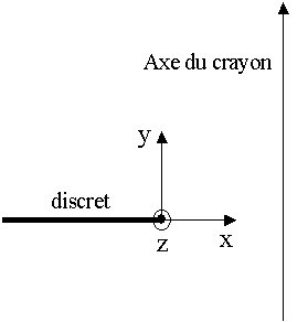
Definition of the local coordinate system.#
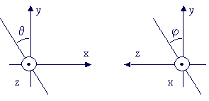
Definition of angles.#
Translational behavior#
Behavioral presentation#
The translational behavior is modelled by a law such as Coulomb friction r5.03.17-gricra-LdC-translation.
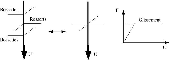
Law of behavior in translation.#
Different types of behavior are affected in different directions:
Management \(x\)
We consider elastic behavior, with an initial force at zero displacement equal to the opposite of the clamping force (the force exerted by the pencil on the discrete squeezes the discrete):
\({F}_{x} = {K}_{N}\Delta x - {F}_{N}^{0}\)
Management \(y\)
An almost perfect elastoplastic behavior is considered to be used to model Coulomb friction and the possibility of sliding. Strength is expressed in the following way:
\({F}_{y}={K}_{T}\left[\Delta y-{U}_{y}^{p}\right]\)
where \(\Delta y\) is the deformation of the discrete according to \(y\) and \({U}_{y}^{p}\) represents the sliding
The sliding criterion is as follows:
\(\parallel {F}_{y}\parallel \le {F}^{S}+\kappa \lambda\) with \({F}^{s}=-\mu {F}_{N}^{0}\)
where \(\kappa\) is a model parameter, \(\lambda\) is the work hardening parameter, and \(\mu\) is the Coulomb coefficient. The flow law is as follows: \({\dot{U}}_{y}^{p} = \dot{\lambda }\frac{{F}_{y}}{\Vert {F}_{y}\Vert }\)
Reference will be made to document [R5.03.09] on the integration of nonlinear laws \(1D\) for the numerical integration of this elastoplastic law of the Von Mises type with isotropic work hardening.
This force is the same for the 4 discretes of the cross system, because they have the same \(y\) direction.
Management \(z\)
It should be noted that the grid-pencil behavior law DIS_GRICRA must be used with a configuration of discrete crosses. It is therefore useless to define a force in the \(z\) direction of the discrete, because the stiffness is « taken up » by the orthogonal discretes (cf. previous section).
Parameters introduced#
The following parameters given in [DEFI_MATERIAU] are used for translational behavior:
KN_AX: axial stiffness of the discrete
KT_AX: tangential stiffness (in the sliding direction) of the discrete
F_SER or F_SER_FO: clamping force of the pencil in the grid, in the axial direction of the discrete
COUL_AX: Coulomb coefficient for the law of friction
ET_AX: work-hardening parameters allowing the law of friction to converge. This setting is optional.
KP: stiffness put in parallel with behavior DIS_GRICRA. This setting is optional. The KP parameter is applied in the x, y, and z directions.
The force required to extract a pencil from a grid is equal to F_SER * COUL_AX (extraction force).
- note
The DIS_GRICRA law of behavior can cause zero pivots and make it difficult to converge the calculation. In this case, it is possible to add a system of 4 elastic springs of low stiffness in parallel to the discretes affected by behavior DIS_GRICRA, to stabilize the structure. The optional parameter KP allows this parallel elastic system to be integrated directly into law DIS_GRICRA without the addition of additional discretes in the modeling. The parameter KP must therefore be a stiffness of low value applied in the directions x, y and z.
Rotational behavior#
Behavioral presentation#
The study of the rotating grid-pencil connection with the bosses-spring system showed that behavior could be described by superimposing three simple behaviors:
a phenomenon of spring sliding orthogonal to the plane of rotation, modelled by a Coulomb law similar to that used in translation,
r5.03.17-gricra-LdC-translation.a phenomenon of sliding bumps orthogonal to the plane of rotation, modelled by a Coulomb law similar to that used in translation,
r5.03.17-gricra-LdC-translation.a bilinear elastic behavior in the plane of rotation, induced by the possibility of detaching the pencil from a boss from a certain angle,
r5.03.17-gricra-LdC-rotation.
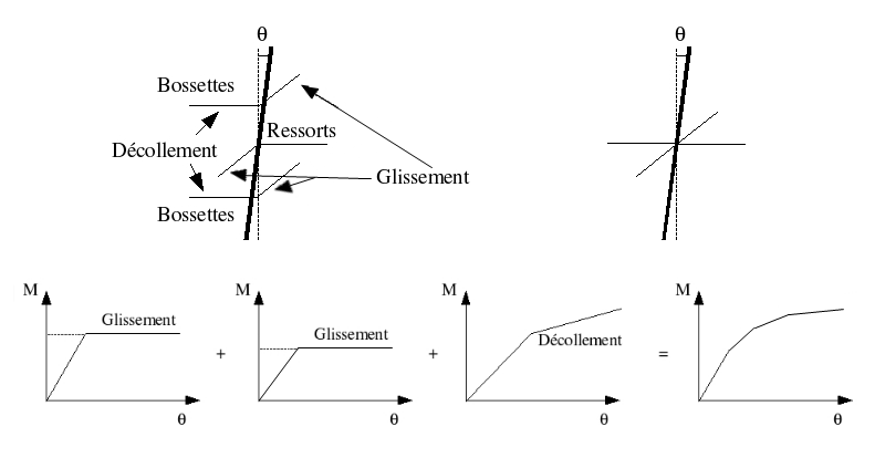
Diagram of the behavior of the grid-pencil connection in rotation.#
It is to ensure this superposition of two elastoplastic behaviors with a bilinear elastic behavior that the configuration of 4 discrete crosses is necessary. If we consider a rotation of an angle \(\theta\) in the global coordinate system corresponding to the local coordinate system of discretes 1 and 2, this angle corresponds to the angle \(\Phi\) of the discretes 3 and 4. It is then sufficient to impose on the discretes the elastoplastic laws on the angle \(\theta\) (of the local coordinate system) and the bilinear elastic law on the angle \(\Phi\) (of the local coordinate system) to have a superposition of the three behaviors thanks to the system of discrete crosses.
Different types of behavior are affected from different angles:
Rotation around the axis \(x\)
Two elastoplastic behaviors of the Von Mises type with isotropic work hardening are considered to model the rotational friction of the spring and bumps. For each law, the moment is expressed as a function of the angle and a « plastic » angle or sliding angle:
\({M}_{x}={K}_{\phi }\left[\phi -{\phi }^{p}\right]\)
where \(\Phi\) is the angle of rotation around \(x\) and \({\Phi }^{p}\) represents the angle of sliding
The sliding criterion is as follows:
\(\parallel {M}_{\phi }\parallel \le {M}^{S}+\kappa \lambda\) where \(\kappa\) is a model parameter, \(\lambda\) is the work hardening parameter, and \({M}^{s}\) is the threshold moment defined by model parameters.
The flow law is as follows:
\({\dot{M}}_{\phi }^{p}=\dot{\lambda }\frac{{M}_{\phi }}{\parallel {M}_{\phi }\parallel }\)
Reference will be made to document [R5.03.09] on the integration of 1D nonlinear laws for the numerical integration of this elastoplastic law of the Von Mises type with isotropic work hardening, by replacing the force by the moment and the deformation by the angle difference.
Rotation around the axis \(z\)
The behavior around the \(z\) axis is considered to be bilinear elastic. The moment around the \(z\) axis is expressed as a function of the angle of rotation around the \(z\) axis in the following way:
\({M}_{\theta }={K}^{{1}_{\theta }}\theta\) if \(\theta \in \left[-{\theta }^{s},{\theta }^{s}\right]\)
\({M}_{\theta }={K}^{{2}_{\theta }}\left[\theta -{\theta }^{s}\right]+{K}^{{1}_{\theta }}{\theta }^{s}\)
where \({\theta }^{s}\) is the angle of change in elastic slope.
Rotation around the axis \(y\)
With regard to the rotation around the \(y\) axis, it is imperative to block this rotation because no law has been identified for this degree of freedom, as the pencil does not rotate. However, in order to limit the poor conditioning of the stiffness matrix, stiffness is introduced into the code, based on the other stiffness in rotation. This stiffness is invisible to the user and has no influence on the calculations, as the corresponding degree of freedom is blocked.
Parameters introduced#
Rotational behavior requires the introduction of 5 parameters, either in the form of constants (ANG1, ANG2,, ANG3,,, PEN1, PEN2, PEN3, PEN4), or in the form of temperature and irradiation functions (ANG1_FO, ANG2_FO, ANG3_FO PEN1_FO, PEN2_FO, PEN3_FO, PEN4_FO). An optional additional parameter ET_ROT allows the sliding behavior to converge. The role of each of the parameters can easily be explained on the angle-moment curve represented in FIGS. r5.03.17-gricra-LdC-rotation and r5.03.17-gricra-glissement-ressort:
Initially, there is no sliding and no detachment, the rotational stiffness is equal to PEN1 (or PEN1_FO).
From the angle ANG1 (or ANG1_FO), the sliding phenomenon on the bumps orthogonal to the plane of rotation is activated, these elements therefore no longer contribute to the rotational stiffness and the slope decreases and becomes PEN2 (or PEN2_FO). The phenomenon of adherence to the spring orthogonal to the plane of rotation is still present.
From the angle ANG2 (or ANG2_FO), compared to the previous situation, the pencil detachment occurs in relation to certain bumps, resulting in a reduction in stiffness. This becomes equal to PEN3 (or PEN3_FO).
From the angle ANG3 (or ANG3_FO) the phenomenon of sliding on the spring orthogonal to the plane of rotation is activated, this one therefore no longer participates in the rotational stiffness and the slope decreases and becomes PEN4 (or PEN4_FO). The phenomenon of sliding on the bumps orthogonal to the plane of rotation is still present.
When unloading, there is still detachment, but there is no longer sliding of the spring and bumps orthogonal, the slope becomes PEN1 - PEN2 + PEN3 (or PEN1_FO - PEN2_FO + PEN3_FO).
When you reach ANG1 (or ANG1_FO) twice from the start of the discharge, the sliding of the bumps is reactivated, and you always have detachment, resulting in a slope equal to PEN3 (or PEN3_FO). The phenomenon of adherence to the spring orthogonal to the plane of rotation is still present.
Depending on the maximum angle reached before discharge, and the value of the parameters, two situations can then occur. Or the pencil is glued back together before the spring slides in the orthogonal plane, r5.03.17-gricra-recollement-crayon:
Starting with ANG2 (or ANG2_FO), we have the pencil stick on the bumps, resulting in a slope equal to PEN2 (or PEN2_FO). The phenomenon of adherence to the spring orthogonal to the plane of rotation is still present.
When you reach ANG3 (or ANG3_FO) twice from the start of the discharge, the spring sliding in the orthogonal plane is reactivated, the slope becomes PEN2 - PEN3 + PEN4 (or PEN2_FO - PEN3_FO + PEN4_FO).
Or the spring slides in the orthogonal plane before the pencil is glued back together, r5.03.17-gricra-glissement-ressort:
When you reach ANG3 (or ANG3_FO) twice from the start of the discharge, the spring sliding in the orthogonal plane is reactivated, and you still have detachment, the slope becomes PEN4 (or PEN4_FO).
Starting with ANG2 (or ANG2_FO), we have the pencil stick on the bumps, resulting in a slope equal to PEN2 - PEN3 + PEN4 (or PEN2_FO - PEN3_FO + PEN4_FO).
The parameter values used for figures r5.03.17-gricra-recollement-crayon and r5.03.17-gricra-glissement-ressort are as follows:
\(ANG1 = 0.001 \ rad\), \(ANG2 = 0.004 \ rad\), \(ANG3 = 0.01 \ rad\)
\(PEN1 = 1000 \ N.m.{rad}^{-1}\), \(PEN2 = 250 \ N.m.{rad}^{-1}\),
\(PEN3 = 90 \ N.m.{rad}^{-1}\), \(PEN4 = 15 \ N.m.{rad}^{-1}\)
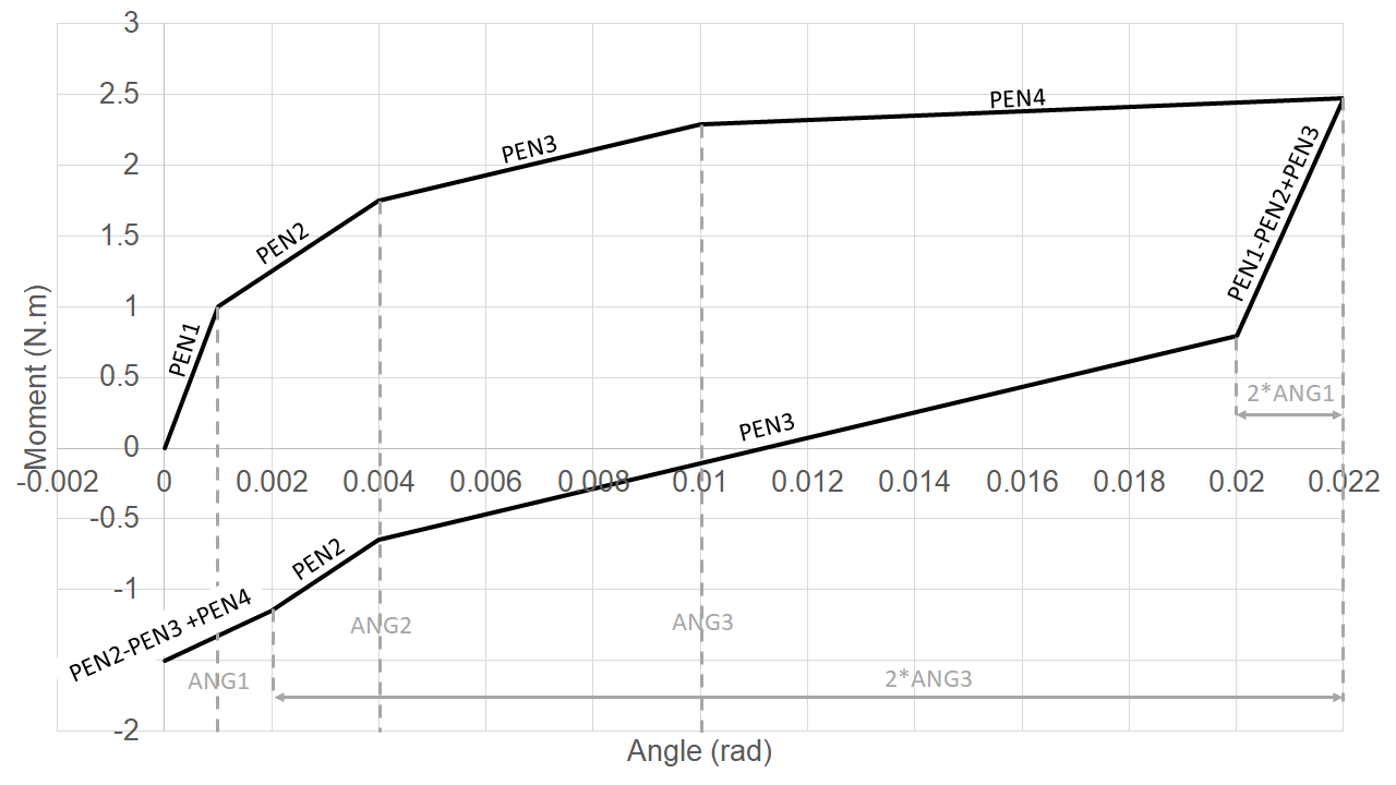
Angle-moment curve on a charge and discharge test in rotation for law DIS_GRICRA. Regluing the pencil before the spring slips during discharge#
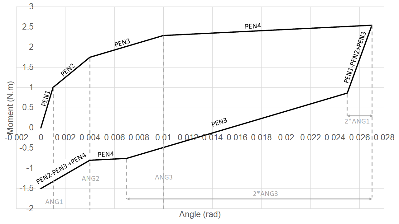
Angle-moment curve on a charge and discharge test in rotation for law DIS_GRICRA. Sliding of the spring during discharge before the pencil is reattached.#
- note
The forces and moments depend on the relative displacements and angles of rotation between the two discrete nodes. In this section, we write the forces and moments at node 2, and we use \(\Delta \alpha =\Delta \alpha (n2) - \Delta \alpha (n1)\) as a writing convention, which represents the « deformation » associated with the degree of freedom \(\alpha\) for the discrete expressed at node \(n2\). The force at node \(n1\) is equal to the opposite of the force at node \(n2\). As a result, the tangent matrix is of the following form:
\({K}^{tan}=\left( \begin{array}{cc}\Underline{K}& -\Underline{K}\\ - \Underline{K}& \Underline{K}\end{array} \right)\)
The behavior of the pencil grid connection is different for each of the degrees of freedom, and independent of the other degrees of freedom. As a result, each of the components of the force depends only on the degree of freedom with which it is associated, and that the blocks \(\Underline{K}\) of the tangent matrix \({K}^{tan}\) are diagonal.
Use#
Type of items#
Discrete elements must be assigned in the [AFFE_CARA_ELEM] command to be able to use DIS_GRICRA (cf. document [V6.02.131]):
Behavior DIS_GRICRA for the grid-pencil link can only be used with discrete elements with two nodes and 6 degrees of freedom MECA_DIS_TR_L. So you have to specify K_TR_L or K_TR_D_L under CARA. Unlike other behaviors for discretes, DIS_GRICRA does not use the discrete stiffness given in AFFE_CARA_ELEM under the VALE keyword. Since the VALE keyword must still be filled in, it is advisable to assign a list of 78 null terms for K_TR_L or 6 null terms for K_TR_D_L.
In the case of a natural mode calculation, the law of behavior DIS_GRICRA is not required, it is therefore necessary to give the rigidities of the discrete that correspond to the elastic regime of DIS_GRICRA, 78 terms for K_TR_L or 6 terms for K_TR_D_L. It is more practical to give the characteristics in the local coordinate system.
AFFE_CARA_ELEM (
    MODELE =model,
    DISCRET =(
        _F (GROUP_MA =( 'meshes1'), CARA = 'K_TR_L', = '', VALE = 'list of 78 terms', REPERE =' LOCAL '),
        _F (GROUP_MA =( 'meshes2'), CARA = 'K_TR_D_L', = '', VALE = 'list of 6 terms', REPERE =' LOCAL '),
        ...
    ),
    ORIENTATION =(
        _F (GROUP_MA =( 'meshes1',),), CARA =' VECT_Y ', VALE = vect_pencil),
        _F (GROUP_MA =( 'mesles2',),), CARA =' VECT_Y ', VALE = vect_pencil),
        ...
    ),
    ...
)
vect_crayon is a direction vector of the pencil. The direction of the pencil must be given under the keyword ORIENTATION.
Moreover, the irradiation field is obtained by combining the lived history (stored as an internal variable) and the increment of the field introduced by the control variables between the current time step and the previous instant.
Definition of the characteristics of the material#
Parameters for behavior DIS_GRICRA should be provided in [DEFI_MATERIAU]. The input parameters for this law are as follows:
Axial sliding behavior: 6 parameters (including 2 arbitrary, purely numerical parameters)
normal stiffness of the discrete KN_AX;
tangential stiffness (in the direction of sliding) KT_AX;
Coulomb coefficient of friction COUL_AX;
clamping force F_SER (sliding limit = COUL_AX* F_SER);
hardening parameter ET_AX (the law of behavior can be equated to perfect plasticity. The work-hardening parameter only serves to ensure the convergence of the calculation;
KP stiffness, paralleling behavior DIS_GRICRA.
Rotational behavior: 6 parameters (including one purely numerical parameter)
successive slopes PEN1, PEN2 and PEN3 of the curve Moment = f (angle);
angles ANG1 and ANG2 of the inflection points of the curve;
work-hardening parameter ET_ROT (parameter only used to ensure the convergence of the calculation.
Clamping forces may vary depending on temperature and irradiation. These dependencies are affected on slopes PEN1 and PEN2 for rotation behavior and on the clamping force F_SER for axial sliding behavior. Dependency functions are defined directly as a FORMULE in the command file.
The names of the parameters followed by the suffix _FO allow you to enter the value in the form of a function. A number of additional parameters, available for this behavior but not included in this document, are explained in [V6.04.131]. The temperature and irradiation dependence parameters of the clamping force are defined in the document [V6.02.131].
Internal variables#
There are 8 of them:
\(V1\): cumulative plastic displacement (axial direction),
\(V2\): touch/friction indicator (1 if sliding, 0 if not sliding),
\(V3\): rotating detachment indicator,
\(V4\): plastic angle (sliding),
\(V5\): cumulative plastic angle,
\(V6\): plastic angle (sliding) nr 2
\(V7\): effort in the direction of sliding (Y)
\(V8\): memorization of the irradiation history (fluence).