1. Geometry of elements#
1.1. 2D linear joint geometry#
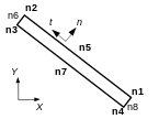
The joint element in 2D is a quadrangle with four nodes (QUAD4) with two short sides and two long sides [12] and [34] (see figure1) which represent the two segments \({\Gamma }^{\text{+}}\) and \({\Gamma }^{\text{-}}\) of an interface (or lips of a crack) between two two-dimensional sub-domains. To distinguish the sides \({\Gamma }^{\text{+}}\) and \({\Gamma }^{\text{-}}\), the local numbering of the nodes must be done as in the figure below:
n
t
n1
n2
n3
n4
Y
X
Figure 1:2D joint element with the correct local numbering.
By convention, face \({\Gamma }^{\text{-}}\) is given by nodes 3 and 4 and face \({\Gamma }^{\text{+}}\) by nodes 1 and 2. Normal \(n\) is directed from side \({\Gamma }^{\text{-}}\) to side \({\Gamma }^{\text{+}}\).
1.2. 2D quadratic joint geometry#
These elements are quadrangle with 8 nodes (QUAD8), the nodes 1, 2, 3, 3, 4, 5, 7 carry mechanical degrees of freedom of movement. Nodes 6 and 8 carry pressure degrees of freedom in order to represent fluid flow for coupled hydromechanical modeling. They are eliminated for pure mechanical models.

Figure2:2D HYME joint element with the correct local numbering.
By convention, face \({\Gamma }^{\text{-}}\) is given by nodes 3, 4, 7 and face \({\Gamma }^{\text{+}}\) is given by nodes 1, 2, 5. Normal \(n\) is directed from side \({\Gamma }^{\text{-}}\) to side \({\Gamma }^{\text{+}}\).
1.3. 3D linear joint geometry#
The 3D joint elements make it possible to represent a surface \(S\) between two sub-volume domains \({\Omega }^{\text{+}}\) and \({\Omega }^{\text{-}}\). They are compatible with subdomain networking. If the volume is meshed with HEXA8, the joints to be used are also HEXA8 (hexahedra with eight knots). If the volume is meshed with PENTA6 or TETRA4, the joints to use are PENTA6 (pentahedra with six knots).
To distinguish between upper surfaces \({S}^{\text{+}}\) (linked to \({\Omega }^{\text{+}}\)) and lower surfaces \({S}^{\text{-}}\) (linked to \({\Omega }^{\text{-}}\)), it is necessary to impose a very specific local numbering of the nodes (see Figure 3).

Figure3: Diagram of 3D joint elements HEXA8 and PENTA6 with the correct local numbering.
By convention, face \({\Gamma }^{\text{-}}\) is given by nodes 1, 2, 3, 4 for HEXA8 (or 1, 2, 3 for PENTA6) and face \({\Gamma }^{\text{+}}\) by nodes 5, 6, 7, 8 for HEXA8 (or 4, 5, 6 for) (or 4, 5, 6 for PENTA6). Normal \(n\) is directed from side \({\Gamma }^{\text{-}}\) to side \({\Gamma }^{\text{+}}\).
1.4. 3D quadratic joint geometry#
These joint elements can be used for coupled HYME models or for pure mechanical models by eliminating DDL of pressure. In 3D they make it possible to represent a \(S\) surface between two volume sub-domains in pure mechanics \({\Omega }^{\text{+}}\) and \({\Omega }^{\text{-}}\). They are compatible with subdomain networking. If the volume is meshed with HEXA20, the joints to be used are also HEXA20 (hexahedra with twenty knots). If the volume is meshed with PENTA15 or TETRA4, the joints to use are PENTA15 (pentahedra with 15 knots).
To distinguish between upper surfaces \({S}^{\text{+}}\) (linked to \({\Omega }^{\text{+}}\)) and lower surfaces \({S}^{\text{-}}\) (linked to \({\Omega }^{\text{-}}\)) it is necessary to impose a very specific local numbering of the nodes (see Figure 4).

Figure4: Diagram of the coupled joint elements HYME in 3D HEXA20 and PENTA15 with the correct local numbering.
For HEXA20, the middle nodes 13, 14, 15, 16 carry degrees of freedom of pressure for fluid flow, and all the others carry mechanical degrees of freedom of movement.
For PENTA15, the middle nodes 10, 11, 12 carry degrees of freedom of pressure for fluid flow, and all the others carry mechanical degrees of freedom of movement.
By convention, face \({\Gamma }^{\text{-}}\) is given by nodes 1, 2, 3, 4, 4, 4, 9, 9, 10, 10, 10, 11, 12 for HEXA20 (or 1, 2, 3, 7, 8, 3, 8, 7, 3, 3, 3, 3, 3, 3, 3, 3, 8, 7, 3, 3, 3, 3, 8, 3, 3, 8, 3, 8, 3, 8, 9 for PENTA15) and face \({\Gamma }^{\text{+}}\) by nodes 5, 6, 7, 7, 7, 7, 3, 3, 8, 3, 3, 3, 8, 3, 3, 8, 3, 3, 8, 3, 3, 8, 3, 3, 8, 3, 3, 8, 3, 3, 8, 3, 8, 3, HEXA20 PENTA15 Normal \(n\) is directed from side \({\Gamma }^{\text{-}}\) to side \({\Gamma }^{\text{+}}\).
1.5. Automatic joint mesh construction#
The MODI_MAILLAGE command used with the ORIE_FISSURE keyword makes it possible to impose the correct local numbering of joint meshes in 2D or 3D (see doc. [U4.23.04]).
In addition, techniques are available to automatically create joint elements in a mesh that does not have them (see [U2.05.07]).