5. Contents of the objects in the sd_fond_fiss#
5.1. Generalities#
5.1.1. . INFO#
K8 vector of length 3:
V (1) contains the SYME keyword value from DEFI_FOND_FISS: “OUI” or “NON”
V (2) contains the CONFIG_INIT keyword value from DEFI_FOND_FISS: “DECOLLEE” or “COLLEE”
V (3) specifies whether the background is open or closed: “OUVERT” or “FERME”
V (4) contains the name of the mesh provided to DEFI_FOND_FISS via the word MAILLAGE
5.2. Description of crack bottom entities#
The list of names of the ordered nodes at the bottom of the crack is given by the vector. FOND. NOEUD. The background consists of a set of contiguous nodes in an element.
5.2.1. . FOND. NOEUD#
This vector contains all the nodes describing the crack bottom. These knots are the intersection of the lower and upper lip nodes.
In the quadratic case, the convention of the ordering of the nodes is not the same as in the connectivity of the meshes. In other words, it does not take into account whether the node is vertex or not. For example, if nodes \({N}_{a}\), \({N}_{c}\), and \({N}_{e}\) are vertex nodes, the vector. FOND. NOEU will be:
\(({N}_{a},{N}_{b},{N}_{c},{N}_{d},{N}_{e},)\)
5.2.2. . ABSCUR#
This vector contains, for each of the nodes of the 3D mesh, the curvilinear abscissa of the projected node on the crack front. The direction of travel of increasing curvilinear abscissa can be defined in several ways:
If the group of elements defining the crack front provided to DEFI_FOND_FISS is oriented, this orientation is maintained.
If not, one of the keywords NOEUD_ORIG or GROUP_NO_ORIGde DEFI_FOND_FISS is required to define a curvilinear x-axis origin. In the case of closed fronts, one of the keywords MAILLE_ORIG or GROUP_MA_ORIGest is also required in order to define a direction of increasing curvilinear abscissa (from the node defined by NOEUD_ORIG/GROUP_NO_ORIG, to the second node end of the mesh defined by MAILLE_ORIG/GROUP_MA_ORIG).
5.2.3. . ABSFOND#
This vector contains, for each of the nodes of the crack front in 3D, the curvilinear abscissa of this node along the crack front. The direction of travel of the increasing curvilinear abscissa is defined in a manner similar to the object. ABSCUR.
In 3D, when the front is closed, the last point on the front is equal to the first. This point is therefore filled in twice in the vector. ABSFON, once with a zero curvilinear abscissa at the start of the vector, and once with a curvilinear abscissa equal to the crack length at the end of the vector.
5.3. Description of the marks linked to the crack bottom#
5.3.1. . NORMALE#
This vector contains 3 real numbers that constitute the components \(({n}_{x},{n}_{y},{n}_{z})\) of the normal to the plane of the lips (case of a plane crack) (see sign convention in [U4.82.01 §3.3.5])
5.3.2. . LTNO and. LNNO#
The concept. LTNO (resp.. LNNO) is a scalar node field (CHAM_NO) that contains for each node of the mesh the real value of the level set tangent (resp. normal) to the crack.
5.3.3. . BASLOC#
5.3.3.1. Local base concept at the crack front#
In 2D, the local base at the crack front consists of 2 vectors with 2 real components. The first is the direction of propagation of crack \(\overrightarrow{{V}_{P}}\). The second is the vector normal to the plane of crack \(\overrightarrow{{V}_{N}}\).
\(\vec{{V}_{N}}\)
\(\vec{{V}_{P}}\)
In 3D, the local base at the crack front consists of 2 vectors with 3 real components per node of the crack bottom. For each node \({N}_{i}\), the first vector corresponds to the local propagation direction \(\overrightarrow{{V}_{{P}_{i}}}\) at the crack edge. The second vector is the normal to the mean plane of the crack \(\overrightarrow{{V}_{{N}_{i}}}\).
Case CONFIG_INIT =” COLLEE “ « « » « « » « » « » « » « «
In the case where the keyword CONFIG_INIT of DEFI_FOND_FISS is set to the value COLLEE, the local base at the bottom of the crack is determined in an analogous manner in 2D and in 3D. The 3D case is presented below only.
\(\overrightarrow{{V}_{{P}_{i\mathrm{-}2}}}\) \(\overrightarrow{{V}_{{P}_{i\mathrm{-}1}}}\) \(\overrightarrow{{V}_{{P}_{i}}}\) \(\overrightarrow{{V}_{{P}_{i+1}}}\) \(\overrightarrow{{V}_{{P}_{i+2}}}\)
Initially, the local bases are built by a pair of nodes at the bottom of the crack, in other words by segment that will be noted \({E}_{i}\). For each face containing \({E}_{i}\) and belonging to the upper and lower lips, we calculate the vector orthogonal to \({E}_{i}\) and in the plane of the face and the vector normal to the face. So, we get two pairs of vectors:
(\(\overrightarrow{{V}_{{P}_{i},S\mathit{UP}}}\), \(\overrightarrow{{V}_{{N}_{i},S\mathit{UP}}}\)) for the upper side
(\(\overrightarrow{{V}_{{P}_{i},\mathit{INF}}}\), \(\vec{{V}_{{N}_{i},\mathit{INF}}}\)) for the underside.
The vectors \(\overrightarrow{{V}_{{N}_{i},S\mathit{UP}}}\), \(\overrightarrow{{V}_{{N}_{i},\mathit{INF}}}\) have the same meaning: they are oriented such that the trihedron (\(\overrightarrow{{V}_{{P}_{i},S\mathit{UP}}}\), \(\overrightarrow{{V}_{{E}_{i}}}\), \(\overrightarrow{{V}_{{N}_{i},S\mathit{UP}}}\)) is direct with \(\overrightarrow{{V}_{{E}_{i}}}\) vector oriented according to the order of the nodes in the background.
\(\overrightarrow{{V}_{{P}_{i},\mathit{INF}}}\)
\(\overrightarrow{{V}_{{P}_{i},S\mathit{UP}}}\)
The local base is calculated as the arithmetic mean of the vectors obtained. In other words, the propagation vector locally at segment \({E}_{i}\) is calculated by the following expression:
\(\overrightarrow{{V}_{{E}_{i},{P}_{i}}}\mathrm{=}\frac{\overrightarrow{{V}_{{P}_{i},S\mathit{UP}}}+\overrightarrow{{V}_{{P}_{i},\mathit{INF}}}}{2}\)
and the normal vector locally to segment \({E}_{i}\) is calculated by the following expression:
\(\overrightarrow{{V}_{{E}_{i},{N}_{i}}}\mathrm{=}\frac{\overrightarrow{{V}_{{N}_{i},S\mathit{UP}}}+\overrightarrow{{V}_{{N}_{i},\mathit{INF}}}}{2}\)
\(\overrightarrow{{V}_{{E}_{i},{P}_{i}}}\mathrm{=}\frac{\overrightarrow{{V}_{{P}_{i},S\mathit{UP}}}+\overrightarrow{{V}_{{P}_{i},\mathit{INF}}}}{2}\)

\(\vec{{V}_{{E}_{i-1},{P}_{i-1}}}\) \(\vec{{V}_{{E}_{i},{P}_{i}}}\)
\(\vec{{V}_{{E}_{i+1},{P}_{i+1}}}\)
\(\vec{{V}_{{E}_{i+2},{P}_{i+2}}}\)
Thus, one local base is obtained per element at the bottom of the crack.
\(\vec{{V}_{{E}_{i-1},{N}_{i-1}}}\)

\(\vec{{V}_{{E}_{i-1},{P}_{i-1}}}\)
\(\vec{{V}_{{E}_{i},{N}_{i}}}\)
\(\vec{{V}_{{E}_{i},{P}_{i}}}\)
Secondly, the local base of a vertex node is calculated as being the arithmetic mean of the components of the vectors of the bases of the related elements at this node. For vertex nodes placed at the ends, the calculated bases are transferred to the end elements.
\(\vec{{V}_{{N}_{i}}}=\frac{\vec{{V}_{{E}_{i},{N}_{i}}}+\vec{{V}_{{E}_{i+1},{N}_{i+1}}}}{2}\)
\(\vec{{V}_{{P}_{i}}}=\frac{\vec{{V}_{{E}_{i},{P}_{i}}}+\vec{{V}_{{E}_{i+1},{P}_{i+1}}}}{2}\)
In 3D, when the background is closed, the last point is equal to the first.
Case CONFIG_INIT =” DECOLLEE “ « « » « « » « » « » « » « » « » « «
In the case where the keyword CONFIG_INIT of DEFI_FOND_FISS is set to the value DECOLLEE, the local base at the bottom of the crack is determined differently in 2D and in 3D.
In all cases, the normal vector, identical for all the nodes of the crack front, is entered directly by the user using the NORMALE keyword.
In 2D, let F be the node of the crack front and A any node of the upper lip, different from F and \(\vec{{V}_{N}}\) the normal defined by the user.
\(\overrightarrow{{V}_{N}}\)
\(A\)
\(F\)
The direction vector is defined as follows:
\(\vec{{V}_{P}}=\frac{\vec{\mathit{AF}}-(\vec{\mathit{AF}}\mathrm{.}\vec{{V}_{N}})\vec{{V}_{N}}}{\Vert \vec{\mathit{AF}}-(\vec{\mathit{AF}}\mathrm{.}\vec{{V}_{N}})\vec{{V}_{N}}\Vert }\)
In 3D, at first, the local bases are built by a pair of nodes, vertices at the bottom of the crack, in other words by segment that will be noted \({E}_{i}\). Let \({A}_{i}\) and \({B}_{i}\) be the vertex nodes of \({E}_{i}\).
The direction vector for element \({E}_{i}\) is defined as follows:
\(\vec{{V}_{{E}_{i},{P}_{i}}}=\frac{\vec{{A}_{i}{B}_{i}}\wedge \vec{{V}_{N}}}{\Vert \vec{{A}_{i}{B}_{i}}\wedge \vec{{V}_{N}}\Vert }\)
Transposing a base defined by element to a base defined by node of the crack bottom is analogous to the case CONFIG_INIT = “COLLEE”
5.3.3.2. Construction of. BASLOC#
The concept. BASLOC is a field with nodes (CHAM_NO) with 9 real components (in 3D). It contains the origin and the vectors of BASe LOCale at the bottom of the crack. For each node in the mesh, the first three components are the coordinates of the projected node on the front, which corresponds to the origin of the local base. The following three components are the coordinates of the 1st vector in the base: propagation direction vector. The last three components are the coordinates of the 2nd vector of the base: vector normal to the surface of the crack, oriented from the lower lip to the upper lip if LEVRE_SUP is defined in DEFI_FOND_FISS. The 3rd vector in the base is not stored, because it is easily determined as being the vector product of the first 2 vectors.
V =. BASLOC (i); |
|
V (1) |
Next coordinate \(x\) of the projected node i on the background |
V (2) |
Next coordinate \(y\) of the projected node i on the background |
V (3) |
Next coordinate \(z\) of the projected node i on the background |
V (4) |
Next coordinate \(x\) of the 1st vector of the local base |
V (5) |
Next coordinate \(y\) of the 1st vector of the local base |
V (6) |
Next coordinate \(z\) of the 1st vector of the local base |
V (7) |
Next coordinate \(x\) of the 2nd vector of the local base |
V (8) |
Next coordinate \(y\) of the 2nd vector of the local base |
V (9) |
Next coordinate \(z\) of the 2nd vector of the local base |
In 2D, we only have 2 components following \(x\) and \(y\), i.e. 6 components for BASLOC.
In 2D, there is only one node at the crack bottom, so all the nodes in the mesh have the same projection on the crack background and the same local base vectors.
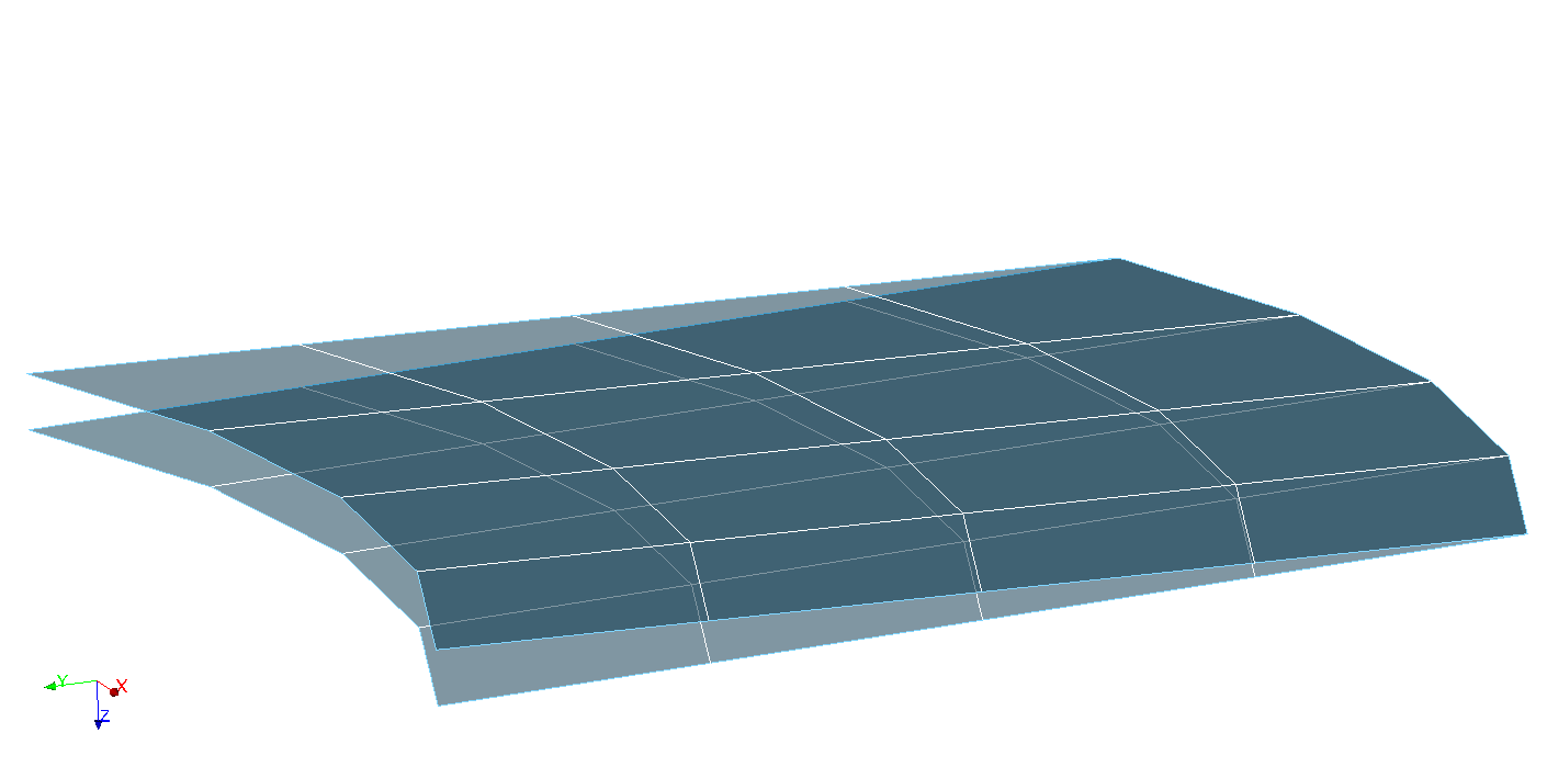
5.4. Description of lips#
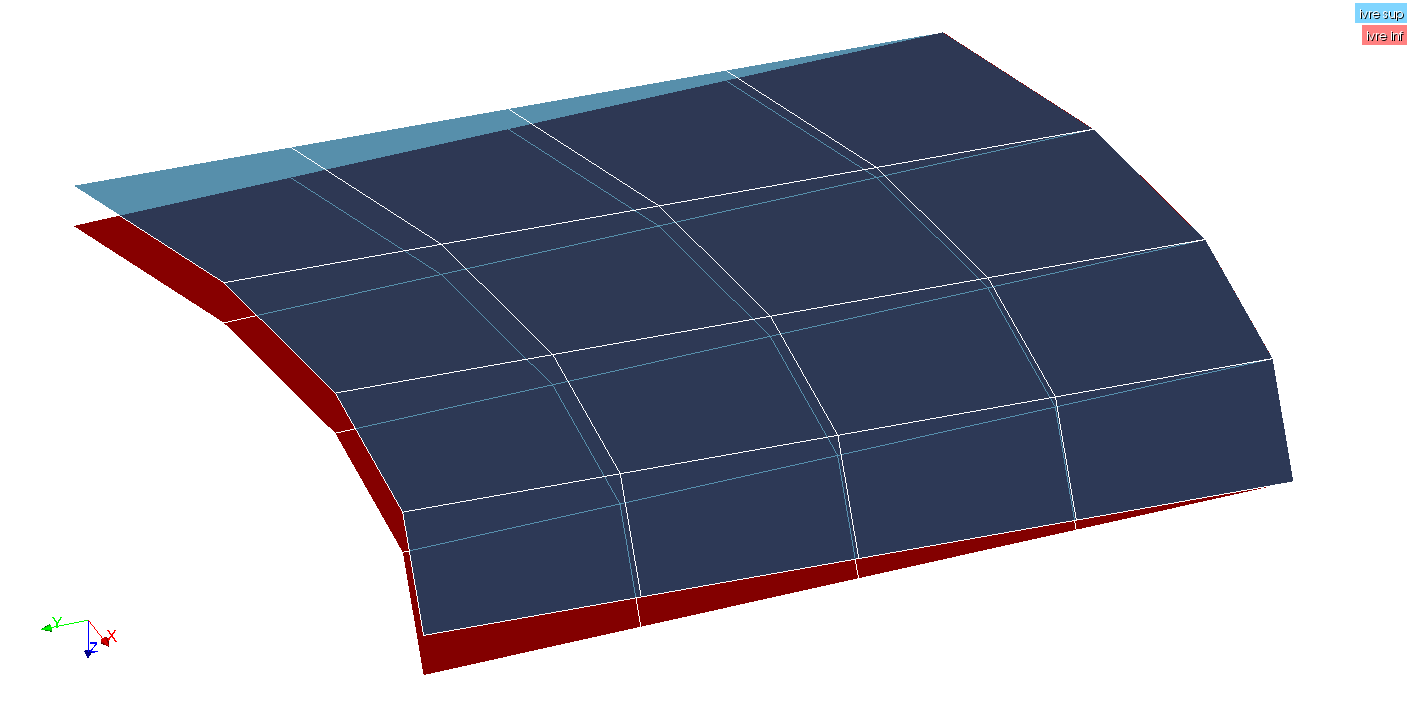
5.4.1. . LEVRESUP. MAIL#
This vector contains the list of meshes of the upper lip of the crack.
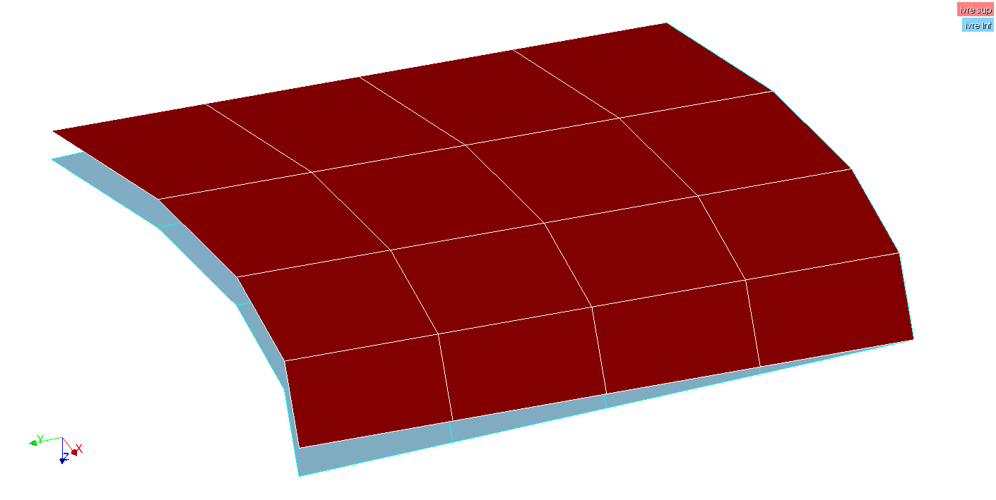
5.4.2. . LEVREINF. MAIL#
This vector contains the list of meshes of the lower lip of the crack.
5.4.3. . SUPNORM. NOEU#
This vector contains the list of the nodes of the upper lip in the direction normal to the bottom of the crack.
5.4.4. SUPNORM. NOEU2#
This vector contains the list of the nodes of the upper lip in the direction normal to the bottom of the crack. This vector is used in the case of POST_JMOD and increases the size of the array from 20 to 100.
5.4.5. . INFNORM. NOEU#
This vector contains the list of the nodes of the lower lip in the direction normal to the bottom of the crack.
5.4.6. . INFNORM. NOEU2#
This vector contains the list of the nodes of the lower lip in the direction normal to the bottom of the crack. This vector is used in the case of POST_JMOD and increases the size of the array from 20 to 100.
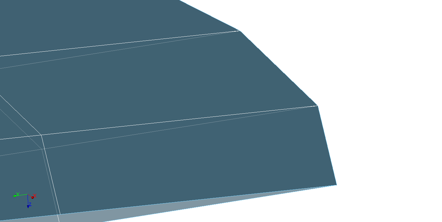
5.4.7. . FOND. TAILLE_R#
This vector contains, for each of the background nodes, an estimate of the maximum size according to the direction of propagation, of the meshes that are connected to them. These sizes are ordered according to the order of the nodes given in. FOND. NOEU.
We note \(\overrightarrow{{V}_{{P}_{i}}}\) the propagation vector from the local base to the background node \({N}_{i}\) and \(\overrightarrow{{a}_{\mathit{ij}}}\) the \(j\) th edge connected to the node \({N}_{i}\).
For each node in the background \({N}_{i}\), the edges \(\overrightarrow{{a}_{\mathit{ij}}}\) are projected onto the propagation direction vector \(\overrightarrow{{V}_{{P}_{i}}}\). The maximum size \({T}_{i}\) of the cells connected to \({N}_{i}\) is the maximum value of the absolute values of its projections. In other words, the size \({T}_{i}\) is equal to
\({T}_{i}\mathrm{=}\underset{1\mathrm{\le }j\mathrm{\le }{\mathit{Nb}}_{\mathit{arêtes},i}}{\mathit{max}}(∣\overrightarrow{{a}_{\mathit{ij}}}\mathrm{.}\overrightarrow{{V}_{{P}_{i}}}∣)\),
where \({\mathit{Nb}}_{\mathit{arêtes},i}\) is the number of edges connected to node \({N}_{i}\).
Edges must be at an angle less than \(70°\) with the propagation direction vector \(\overrightarrow{{V}_{{P}_{i}}}\) to be projected onto them. If not, they are ignored. For a \({N}_{i}\) node, if no edge meets this condition, an alarm is issued and the \({T}_{i}\) size is zero.
When the elements connected to the crack bottom are quadratic, the segments of the crack bottom contain a node in the middle. For each of these segments, the mesh size assigned to its middle node is the average of the sizes calculated at its top nodes.